Virtual Turing-Welchman Bombe - Tutorial
Introduction
This tutorial will explain how to use the Bombe Simulator as well as the Checking Machine Simulator for any Enigma encrypted message (and crib; more on that later). It will not go into detail when it comes to explaining why the Bombe works or how it is constructed. The Bombe Simulator aims to be as accurate as possible but there may be differences compared to how a real Bombe would work. To see a fully functional Bombe Rebuild in action, we would recommend that you visit The National Museum of Computing (TNMOC), which is on Bletchley Park, but outside the main Bletchley Park Museum. For further information on Enigma and the story on how it was broken, we also highly recommend a visit to Bletchley Park itself.
A Few Words on the Enigma Machine and the Bombe
It is expected that the reader has basic knowledge of the workings of the Enigma machine. However, a short overview is provided here to explain some of the terms used when working with the Bombe. To find out more and use an Enigma machine for yourself, please see our 3D web-based simulation, Virtual Enigma at https://enigma.virtualcolossus.co.uk
The Enigma machine works by creating an electrical circuit using an input letter from a keyboard, several scrambling stages and a lamp showing the resulting scrambled letter. Each scrambling stage swap the input letter for some other letter which is passed to the next stage. The stages are:
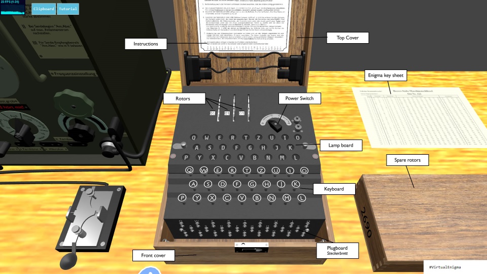
- The plugboard. The plugboard provides the possibility to swap up to ten pairs of letters by connecting cables between the letters. If for example a cable is connected between A and E, pressing A on the keyboard will send an E to the next stage.
- The rotors. The most common Enigma machines have three rotor slots with eight rotor models, with different internal wiring, to choose from. The rotors are labelled with Roman numerals: I to VIII. Each rotor has a ring with either the alphabet, or numbers representing the alphabet, printed on it. The rotor can be rotated so that a certain letter is seen in a window on the Enigma. This is called the position of the rotor. The ring can be rotated in relation to the rotor, this is called the ring setting. For more details see the chapter on this below.
- The reflector. After passing the reflector the signal will pass through the rotors and plugboard again, in reverse order. There are three different reflector models commonly used, these are labelled A, B and C.
To encrypt or decrypt a message, an Enigma machine operator had to set up several things on the machine. These, when taken together, constitutes the key for the message.
The different parts of the key are the following:
- Which rotors are used, and in what order are they put into the Enigma.
- The starting position of the rotors. For example, if the starting position is 'HEJ' the leftmost rotor will be rotated to H, the middle to E and the rightmost to J.
- The ring setting of the rotors. This is written in the same way as the starting position: a letter for each rotor.
- The plugboard connections. This is written as a string of 10 pairs of letters.
If we use a three rotor Enigma with eight available rotors to select from and must use ten cables to interconnect twenty letters on the plugboard, the keyspace will look like this:
Number of possible ways to select rotors and rotor order: 336
Number of possible ring settings: 17,576
Number of possible rotor starting positions: 17,576
Number of ways to connect 10 cables in the plugboard: 150,738,274,937,250
Clearly, the largest contribution to the key space is the plugboard, by far.
The purpose of the Bombe machine is to aid in finding the key used for a message, more specifically, it will help with the plugboard settings. The machine can be seen as several simplified Enigma machines connected in a way that will allow it to rule out many impossible plugboard settings and provide the remaining, potentially correct, settings to the user for further analysis. The Bombe can search through all 17,576 rotor starting positions, but rotor order and types needs to be tested manually.
More details about rotors and drums

For every key press on the Enigma the rightmost rotor will move one step, when it reaches a certain position, it will trigger the middle rotor to move one step. This is called a turnover. In the same way the middle rotor will make the leftmost rotor move. A piece of metal called a “notch” on the rotors will trigger the mechanism that activates the next rotor. Usually there is only one notch on a rotor, so that it will trigger one turnover per revolution, but some rotors have two notches.
The ring setting on the Enigma rotors does not change the actual scrambling carried out by that rotor. The wiring inside a rotor is always the same for that specific rotor. The ring setting only changes at which position the rotor scrambles one letter to another.
This means that a rotor with its ring set to A, in the position A is equivalent to the same rotor with the ring set to B and the position set to B, except that the turnover position will move one step as the notch is fixed. We will see later how the turnover positions can affect the Bombe process.
The Bombe uses drums that scrambles letters in the same way as the Enigma rotors. However, they don’t have a notch or a ring setting. There is still a turnover, but it always happens on the “Y” position of the drums, on the Bombe, this is called the Carry. The drums are recognised by a distinctive colour, each colour corresponds to one of the Enigma rotors, I to VIII. The drums have similar wiring as their Enigma counterparts but there are differences. Probably by mistake, drums I, II, III, VI, VII and VIII on the Bombe are one letter ahead of the corresponding Enigma rotors. Drum IV is two steps ahead, and rotor V is three steps ahead.
Moving around the Virtual Bombe
There are two modes when using Virtual Bombe, the Use mode, and the View mode. You can tell which mode you are in by looking for the icon in the bottom-right corner of the window. The icon shows the use mode where you will be able to use the mouse cursor to interact with the Bombe, and the icon shows view mode, where you will be able to look around the 3d environment. In both modes, the method of moving around is the same; use the W and S keys to move forwards and backwards, and the A and D keys to move left and right.
When in Use mode, you will be able to see the mouse cursor on screen and you’ll be able to click and drag the Bombe drums, switches, and connectors. When in View mode, the cursor will not be visible and moving the mouse around will change your point of view.
To change from View mode, just click the left mouse button which should give you control of the mouse cursor again. To return from Use mode, just click the mouse cursor anywhere outside of the main Bombe model (anywhere the cursor is an arrow rather than a hand icon).
Try moving around the Bombe machine now in View mode using both the keyboard and the mouse, see if you can get all the way around looking at each of the four sides of the Bombe machine in turn.
Displaying the Bombe in 3D takes quite a large amount of processing power, if your computer isn’t quite up to the task and you’re finding the movement jerky and unresponsive, try shrinking the size of your browser window to a smaller size which should help.
Anatomy of the Bombe

The front of the Bombe has 36 drum banks organised in three rows of 12 drum banks per row. A drum bank consists of three drums representing the three rotors of an Enigma machine. The top drum corresponds to the slow leftmost rotor of the Enigma machine, and the bottom drum to the rightmost rotor. Note that a drum bank is not equivalent to a complete Enigma machine, just the rotor scrambler part, including the reflector.
There are three sets of control logic on the Bombe. These are referred to as chains. The three chains provide the operator with the option of running three different messages or setups at once if the number of drum banks needed for each set-up is not higher than 12.

On the front are also three indicator drums which are used to read part of the possible solution once the Bombe stops. There is also a start and a stop button to control the motorised mechanics.
The reflector of the Enigma machine is implemented as a panel connector on one side of the Bombe. There are three panel connectors, one for each of the 12 sets of drum banks.
On the back of the Bombe there are several 26-pole jacks. Cables with 26 conductors (one conductor for each letter in the alphabets) are used to connect the jacks in different ways depending on the analysis of the encrypted message, described below. There are special jacks used to inject a test current into the system as well as display the result.
The other short side of the Bombe has a number of switches used to select on which lead of the 26-pole jack (which letter) to inject a current into the system. There are also some switches for controlling the stepping mechanism (called carry) of the drums on the front. Finally, there is a 'letter box' type display which will, once the Bombe stops, indicate which letter is the possible solution for the message currently set up on the Bombe. A lever to the left of the letter box display is used to re-start the Bombe once it has automatically stopped.
Making a Menu from a Crib
The first step of trying to retrieve the key used to encrypt a message is to create a diagram called a menu. From the menu it is possible to see if the message is likely to be successfully processed on the Bombe. The menu also tells us how to connect the cables on the back of the Bombe for the message in question.
To create a menu, we need a piece of the clear text corresponding to a part of the encrypted message. This is called a crib. The analysts at Bletchley Park knew that many messages contained stereotyped phrases, this made it possible to guess the crib. Another fact that helped is that an Enigma machine cannot encrypt a character to itself, so in many cases it could immediately be seen if a stereotyped phrase or word was not present at a specific position in an encrypted Enigma message.
If they were able to find the key for a single message received during a day, they would be able to read all the messages received during that day, since the same key was used for all messages of a day for a given Enigma network.
As an example of how to create a menu we use the following crib:
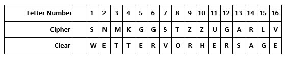
WETTERVORHERSAGE is the clear text and means "weather forecast" in German.
We then draw a graph where links are added between a scrambled character and its clear counterpart. The aim is to have one connected graph with as many loops as possible. If a menu does not contain enough letters and/or loops there will be many false stops of the Bombe meaning that there will be a lot of work until we can determine the correct key.
Virtual Bombe has a menu generator1 which will help you with this step. Click on the icon to open a new page ready to create a new menu. An example menu will be loaded where we can see how this works. The cipher text in this example is QFZWRWIVTYRESXBFOGKUHQBAISEZ and the crib we want to fit is WETTERVORHERSAGEBISKAYA, you should be able to see these shown at the top of the screen.
Note how the two letter S in the text are shown in red, this is because we know that Enigma can not encipher a letter as itself, meaning that this must be an incorrect position for our crib. We can slide the crib along by clicking the arrows to the left and right of the crib text. Click the arrow pointing to the right to move one step.
Now, it’s an even worse fit, we have a clash on the letters V, E and A. We should move another step which gives a clash on the letter R, still not correct. Keep moving the crib until you find a place where there are no clashes between the two texts. This means that there is a possibility that this is the place where this crib is written in the cipher text.
The staff at Bletchley Park would then draw the menu from these links, drawing each linked letter (for example R--W is the first) with a line between. We can start to build this by typing in right hand text window. On the next new line, type R—W, this will create two nodes with a line between them. A loop from this first letter can be found in this example; there is a link from the W we just drew to the letter E. Let’s add that to our menu generator script. On the next line, type W--E, after a brief pause, the generator will add a line to E. We can continue to find other links to make a full loop, complete the loop on our script. From E--O, then another from O--S and finally one from S back to our original letter R, S--R. Note: If your node letters don’t join up, make sure you’re typing them all in the same caps (all capital letters). More options for the designer script, such as arrows or colouring, are available by checking the syntax help button in the top right of the screen.
You can either continue in this way to join up all the letters linked between the cipher text and the crib, or for a faster option, click the Auto Generate Menu which will add all of the linked letters for you. The visualization of the graph will try to automatically fit all the nodes and edges within the screen which may take a second or two to settle down. If you find some edges are overlapping, then you can adjust the nodes by clicking and dragging them around until you get the best view with the least edges crossing.
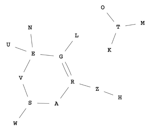
Let’s now go back to look at our simpler example from the last page, the cipher text is SNMKGGSTZZUGARLV, and the crib is WETTERVORHERSAGE. Click the Edit Cipher/Crib button and enter these two values. Once you have updated the texts, you can see that there are no clashes, click the Auto Generate Menu button to draw our graph, again, you may need to drag a few nodes slightly so they’re not crossing.
The menu now consists of two separated graphs which is generally not wanted. We therefore discard the letters O, T, M, W and K from our menu.
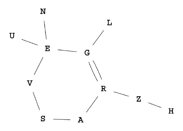
Find, and delete, the following lines in our script T--O, M--T and K--T. It is also convenient to have no more than 12 links in a menu. As mentioned previously, we can test three rotor configurations at the same time if the menu under test uses at most 12 drum banks. We remove the letter W to get only 12 links, find the line S--W and delete it. Removing W does not break any of the two loops that are present in the menu.
Note how the letter G--R has two lines. This is because we have two links in our cipher/crib with both those letters in. We can do that on the script by making sure that you enter one as G--R, then the other as R--G. The menu generator knows to link those with two separate lines.
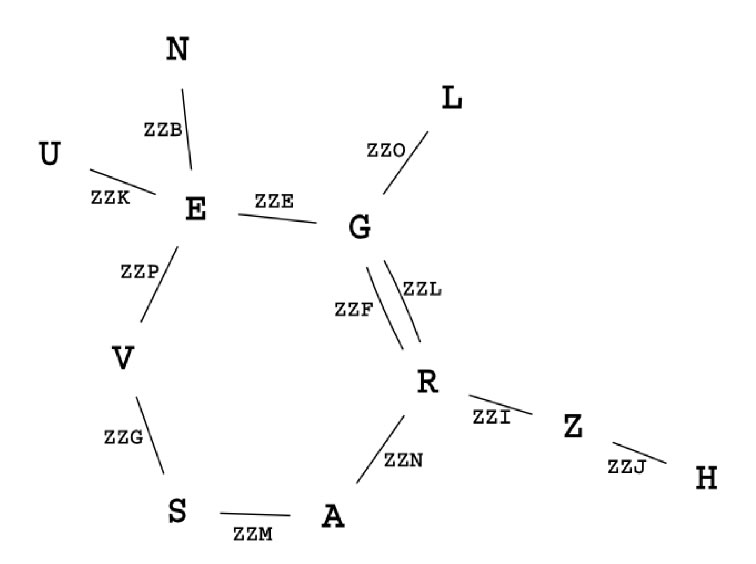
To this graph we then add additional information. We will assume that the Enigma rotors would be set to ZZZ before the message was encoded, and that no middle rotor turnover had happened. The Bombe considers ZZZ the 'home' position.
Under the circumstances above, the first letter of clear text would have been enciphered with the Enigma rotors set to ZZA, the second letter with ZZB and so on. Write the assumed enigma rotor position for each link in the graph.
This should be your final resulting menu graph.
To start to convert this graph into something that we can wire up the Bombe with, assign a drum bank to each link in the graph and write the number of the drum bank in a table together with the assumed rotor position. Try to get a continuous sequence of drum banks following the flow of the graph. This simplifies the way the wires are connected on the back of the Bombe by allowing us to use special bridge connectors that connect the output of one drum bank to the input of the very next one.
We will take the following route through the graph to maximise this effect: U -> E -> G -> R > A -> S -> V -> E -> N and H -> Z -> R -> G -> L.
Pick a central letter in the graph, one with lots of connections, and denote it 'input'. This is where the test current will be injected. In this case we will pick the letter G. Finally, we make another table where we map each letter in the graph to the connections that are in use on that letter. For example, U is only connected to the input of drum bank 1. E however is connected to both the output of 1 as well as the input of 2, and to the output of 7 and input of 8. When a letter is connected to the output of one bank and the input to the next, we write that connection within parenthesis. This is a reminder that we can use a bridge connector for this connection.
The last step is to decide which letter to test. It should be a letter that is present in the menu, but not the same or next to the input letter. We choose A and write this on the menu as "Current entry at A".
This completes the creation of the menu which should now look like this:
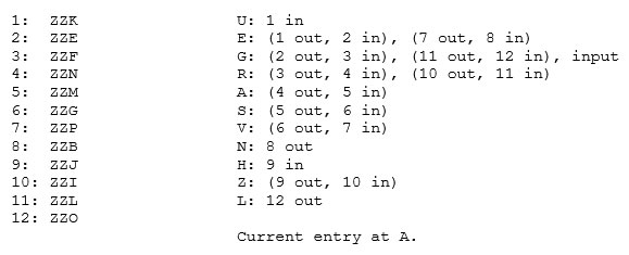
This menu will test the hypothesis that A was connected to G on the plug board of the Enigma machine. However, due to the clever construction of the Bombe, even if this hypothesis turns out to be false (which is likely) we will still get the correct plugboard connections.
1 The menu generator is using a Javascript graph visualization library code from arborjs.org
Setting Up the Menu on the Bombe

TL;DR : Watch the video - You Tube on How to setup the Bombe machine
First, we select which set of rotors we will try and in which order. Since we use no more than 12 drum banks, we can try three rotor orders at once if we wish. However, for now we will just try one order; II, V, III, which happens to be the correct one. Use View mode to get in a good position so you can see both the front of the Bombe machine and the Drums on the table to the left (as above), then click the mouse button to switch to Use mode.
Seen from the front drum bank 1 consist of the three rotors at the very top left, number 2 is to the right of bank 1 and so on. We want to fit drum II onto the top/slow row so click and drag on the drum labelled “II Maroon” on the table and drag it onto the top left commutator. For a short while, after dragging on a new drum, a button will appear at the top left of the screen marked “Duplicate Row”. Click this to duplicate this rotor on all drum banks of that row. Now repeat for the middle row of drums, drag the drum “V Brown” onto the middle row and duplicate it, then finally, drum “III Green” onto the lower/fast row. If you accidentally fit the wrong drum, click and drag it off the commutator and release the mouse button.
Next adjust the drums to the correct letters according to the menu. Drum bank 1 should be set to ZZK; Each drum can be rotated by clicking then dragging with the mouse. Keep the cursor within the drum while you rotate (moving outside and releasing the mouse button will remove the drum). Leave the top and middle drums in position Z and rotate the bottom drum until the pointer is next to the letter K.
Repeat this for the other 11 drum banks and make sure to set the drums to the letters as per the menu.
By default, the Bombe simulator is set to use the B reflector. There are cases when other Enigma reflectors have been used. To change this, move around to the left side of the Bombe click on the reflector panel connector to change it. The left hand one is for Chain 1 over to the right hand for Chain 3. In our case we should leave it as it is, using reflector board B.
The wiring of the menu is done on the back of the Bombe. Each jack can connect either a 26-way cable (one lead for each letter in the Enigma alphabet), or a special bridge connector. A bridge connector connects one jack with the one directly beneath it and it also provides a jack of its own. There are three sets of three columns for each of the Chains: a column with the letters Z-A, which is known as the diagonal board; a column of jacks labelled “CO1”, “CO2” etc, these are commons and each set labelled “CO1” are connected together, the same goes for “CO2” and so on; and a column with each of the drums connected from the front labelled “IN” and “OUT” for each of the 12 drums.
First, we place the bridge connectors. These should be placed on the connections we wrote within parenthesis. To bridge the output of drum bank 1 to the input of drum bank 2, click on the jack labelled "OUT1". To remove a bridge connector, click on it a second time. Repeat this for all possible bridge positions in the menu.
We then proceed to connect the entire menu from top to bottom, starting at U. According to the menu U should be connected to the input of drum bank 1. Click on the jack labelled U in the leftmost column of jacks, a wire should appear ready for connection. Move the second plug until you are over the connector marked “IN1” at the top of the third column, click to fit the connector. If you wish to move the connector, you can click on the second placed plug (the one we put into IN1) then move it to another socket. To remove the wire entirely, click on the first placed plug (the one in the U socket). Hovering over either of the plug sockets will light up the cable, this will be useful later when more cables are connected to trace what plugs into what sockets.
The next letter on the menu, E, is connected to two bridges. We therefore need to use one of the sets of common jacks. First connect the E jack to one of the jacks labelled CO1, it does not matter which one. Do this by first clicking on the E socket, a cable will appear connected between the selected jack and the closest free jack. Move the connectors of the cable so that it stretches from E to CO1 then click again to connect it. Then create a new cable, this time from one of the other CO1 jacks to the jack on the bridge connector spanning OUT1 and IN2. Add a third cable connecting yet another CO1 with the jack on the bridge connector between banks 7 and 8. This completes the E-line on the menu.
Continue like this for all letters on the menu. The current input, which we selected at letter G, is one of the jacks labelled CH. These are on the top of the column second from right. Select CH1 as input for this menu.
Now, move around to the right side of the Bombe. You will now see a section with a lot of switches, a letterbox display, and a lever (next to the letterbox). There are four columns of switches, one for each set of 12 drum banks (chains) of the Bombe, and one auxiliary chain that can be used for more advanced menus. There is one on/off switch for each chain, and then one switch per letter in the Enigma alphabet. This allows the user to select on which of the 26 terminals (A-Z) a test current will be injected. Below the A switches there are three switches. "Carry Home" is used to enable the carry mechanism on all drums until they are in the initial, or home, position. It is a way to quickly reset the Bombe to its starting state. "Double Input" is used, sometimes together with the Aux Chain, for advanced menus and will not be discussed further. "Carry" is enabled to start the regular carry mechanism so that the middle drums advance one step for each full revolution of the fast drums and so on. Switch on the following three switches: "Chain 1" at the top, the switch "A" of Chain 1 and "Carry" at the bottom.
Finally, click on the two power switches (above the letterbox) so they are both on.
Running the Bombe
The menu is now set up and the Bombe is ready to start working. On the Bombe front, to the right of the three golden indicator drums, are two buttons. The left button starts the Bombe. The right button stops the Bombe. Press the start button and watch as the drums spins; the Bombe has now started to search through a part of the Enigma key space for a setting that satisfies the current menu.
It will take a little while for the Bombe to work through all positions and it will switch off automatically if it finds a valid “stop”. Watch as the top drum do a full rotation checking each of the combinations in turn and then it does a half-turn while the carry mode rotates the drum below. This is repeated with a full rotation of the top drum and another half-turn for carry, meaning the middle drums turn two times for every three turns of the top ones. Once the middle drum does a full rotation, it also turns the lowest set of drums until either a stop is found or the whole set of 17,576 options have been checked. While you wait (and if your computer can cope with the extra graphical load!) walk around the back of the Bombe and click the Open Bombe icon . This will allow you to see some of the inner workings moving as the Bombe does its job.
Dealing with Bombe Stops

It is likely (and was desired to verify that the Bombe was working as it should) that there will be more than one stop before the Bombe has finished searching though the current part of the key space. Only one of these stops will be the correct stop corresponding to what was used on the Enigma machine. The other stops are random, a result of mathematical probability. Each stop must be checked for validity. We do that with the Checking Machine.

When the Bombe stops the first time the golden indicators show: SNY and the letterbox display on the side of the Bombe indicates the letter D. We write this as SNY:D. Once the stop has been written down the Bombe can be restarted to continue its search. This is done by first pressing the start button on the front (the left of the two buttons), and then briefly lifting the lever to the left of the letter box display on the side of the Bombe. While the Bombe continues to search, the first stop can be tested on the Checking Machine.
The Checking Machine
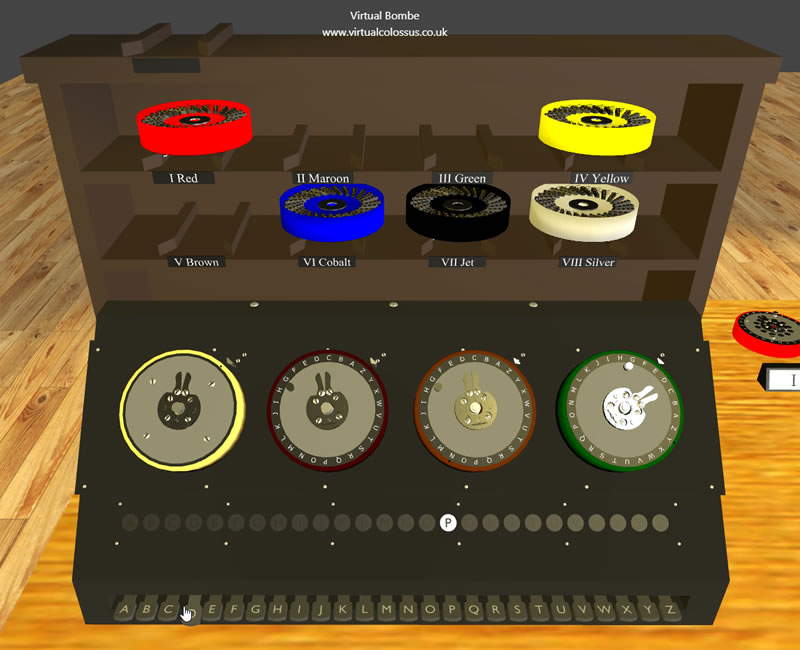
The Checking Machine is the device on the left-hand side of the table. The Checking Machine is like the Enigma, it has a keyboard, four drums, a reflector, and lamps to show a scrambled letter. However, it does not have a plugboard and no mechanisms to move the drums.
To the left is a cartridge that acts as the reflector. It can be replaced to match different reflectors by clicking on it. Since the B reflector was used for this message and B is the default on the simulator, we do not have to change this. Since our message stems from a three rotor Enigma a dummy drum with a one-to-one mapping of the letters of the alphabet is used to the far left.
The dummy drum is yellow with no letter markings and is on top of the stand behind the machine, we can use this to simulate a 3-wheel Enigma. Click and drag this drum to the commutator on the far left of the Checking Machine. Next, we need to add the other three drums until they are set up as the Bombe: II, V, III (from left to right). Drag those drums from the stand onto the correct positions.
On a piece of paper, write down the letters from the menu in a column:
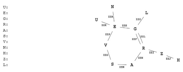
Next, set the rings on the drums to the letters indicated on the stop, in this case: SNY. To set the drum rings, drag the outer coloured edge of each drum, rotating the drum with the mouse. The ring setting is indicated with a small black dot on the outer rim of the drum. When you are done the dots should be by the S, N and Y letters respectively. Hint: You may find this easier to see by crouching down and moving closer (press the Shift key)
The Bombe suggested that on the Enigma plugboard the letter G is connected to the letter D. Write the letter D next to G.
On the menu graph, if we want to move from the letter G (our selected input letter) to the letter E we need to set the drums to ZZE. Rotate the drums on the Checking Machine to ZZE. If we now press the D key (the suggested plug board connection of G, also called stecker partner) we will see what the possible stecker partner of E is. In this case P lights up; write P next to E. Using this newly found stecker partner of E we can now use that to check the possible stecker partners to the letters in the menu graph that connects to E and so on.
Continue to follow each link in the graph in this manner and make a note of all the suggested stecker partners. The next one might be from the letter E to U which means we set the drums to ZZK and press the P key (the stecker partner of E) which should give the letter W. If you arrive at a letter for which you already have a stecker partner, the result should be the same letter as before. If it is not, then we have a contradicting result and therefore this stop is false, we need to go back to the Bombe and find a new one. Remember that a letter can very well have itself as a stecker partner. This is the same thing as an unconnected letter on the plug board on the Enigma and is sometimes called a self-steckered letter.
The complete result for this stop should look like this:
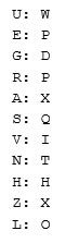
Here we have two contradictions: X cannot be connected to both Z and A, and P cannot be connected to E and R.
This stop is therefore false.
The next stop of the Bombe should be DKX:Q. Repeat the procedure on the Checking Machine, this time with the rings on the Checking Machine set to D, K, X and the suggested stecker partner of our input letter G on the menu is now Q. Once all links in the graph are tested the result should be:
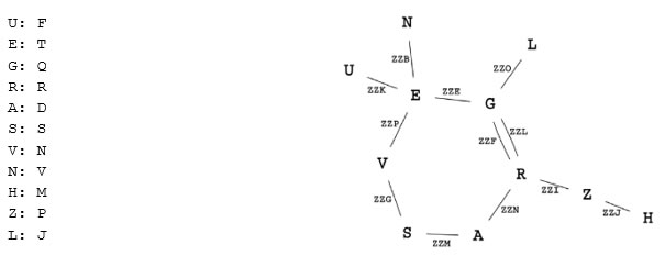
In this case there are no contradictions. Instead, it is reassuring that V has N as a stecker partner and that N has V. This stop, DKX:Q, passes the test and is worth investigating further. Even though we found no contradictions there is a possibility that it still is not the correct solution.
Getting the Enigma Message Key
To investigate a possible key further we will use a simulation of a real Enigma machine. In a new web page, go to https://enigma.virtualcolossus.co.uk/ and click on Run Virtual Enigma. Make sure that the Enigma model in the top right is set to the Enigma Model I then click on the lid of the Enigma machine to open it. Virtual Enigma uses the same keys & use/view method to move around as Virtual Bombe.
First, we will set up the Enigma machine as we currently think our solution should be set up. Click on the grey knob that is either left of the P lamp or right of the L lamp. This will "unscrew" the lid and open the Enigma. Click the gold-coloured lever to the left of the rotors to remove the current rotors.
We currently have rotors I, II and III and we want to switch these for our rotors II, V and III.
Click and drag rotor I onto rotor II and release the mouse button, these two should swap places.
Click the spare rotor box to open it, then drag the middle rotor (which is currently I) onto rotor V (the right hand one in the box) to swap those. You should now have the correct sequence, II V III, in place left to right.
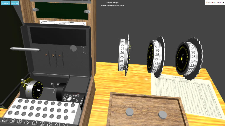
Next, we set the ring settings to DKX. To change a ring setting, drag a rotor until you can find the small pin which will currently be next to the 01 position. Click the pin to release it. Now drag the number tyre to set the ring for the number 04 (letter D) next to the pin. Now click the pin again to fix this value. Set all three rings to D, K and X respectively (04, 11 and 24).
Click on the gold-coloured lever to return the rotors to the Enigma and finally, close the lid by clicking on it.
Set the rotor starting position to ZZZ (26,26,26) by dragging up or down on each rotor and drag the power switch (just to the right of the rotors) two positions to the left to power on Enigma.
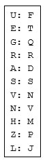
Next, we will connect the plug board settings we know of. Click on the blue plug board connector button just to the bottom-left of the Enigma machine and open the front panel. This should give you a front view of the plugboard itself. Ten cables are available, connect these as per the results from the Checking Machine: U to F, E to T and so on. Letters that should be connected to themselves (R and S) should be left unconnected as the default state of a letter is to be self-connected.
With all the cables connected, click on the blue plug board connector button again to get back to the top view of the Enigma machine.
To compensate for the previously mentioned errors on the Bombe drums (see page 3), and given that we are using rotors II, V and III, we translate our assumed starting position ZZZ into YWY, so set the starting positions of the rotors to 25, 23 and 25.
Now, let's try to decrypt the message! With the starting position set to YWY, take the position of an Enigma operator receiving an encrypted message. Type in the ciphertext SNMKGGSTZZUGARLV. The results are like the ones we want, but not quite right: WETCERVXRHERSAGE. The C and the X are not the expected letters. This is most likely because we do not know of all the plugboard connections yet.
Let's look at C first. We tried to decrypt the letter K and got C instead of the expected letter T. We could then potentially get the desired letter T by connecting a cable between C and T on the plugboard. However, T already has a cable - connected to E. So, our next strategy is to find a letter which, enciphered through the rotors alone at the rotor position of this letter (ZZD in Bombe rotors), would be enciphered to E. Since E is connected to T this would result in the desired output. Go back to the Checking Machine and set the drums to ZZD. Press the keys on the keyboard until you find the one letter that enciphers into E. That letter is I. On the plugboard, connect a wire between I and K.
Looking at the next problem, we got an X but wanted an O. Neither X nor O has a cable connected. Connect the last cable between X and O.
Reset the Enigma to YWY and try to decrypt the ciphertext again. We now get the expected result: WETTERVORHERSAGE.
All the letters in our crib are now correctly deciphered. Does this mean that we have the correct key? Yes and no. Since we have all ten plugboard pairs, that part of the puzzle is most likely solved (given that our two guesses proved to be correct). But the ring setting and the rotor starting positions are probably not entirely correct.
If we had a longer section of ciphertext than just the part of the crib (which must have been the normal case) then at some point it would be expected that the text being deciphered would switch from understandable text to gibberish. If such a sudden switch from clear to scrambled text appears it is fair to assume that what happened was that the leftmost and/or middle rotor has advanced one step where it should not have. This can happen either on "our" side or it could have happened for the original cipher clerk, but not us. When we suspect that a turnover has occurred at the wrong position, we can adjust the ring and starting position one step at a time until we find the correct notch position. In the worst case we need to do this 25 times per rotor, so this is not an overly difficult process. It should be noted that if a turnover happens in the middle of the crib the process as described in this document will not work.
Summary
We have now seen an example of how an encrypted Enigma message can be broken given a crib. From the crib a menu was created, and this menu was then used to set up the Bombe for the message in question. The Bombe stops were checked in the Checking Machine, and the promising stop was further processed in an Enigma machine to get a more complete key.
We cheated a little by knowing in advance which rotors and reflector were used and in which order the rotors were mounted in the Enigma. In practice the same menu would have been set up on several Bombes. Using three chains on the Bombe it was possible to check three different rotor orders on one Bombe.
This procedure had to be repeated every day and for every Enigma network that was of interest.
A lot of work was needed to maintain this day after day, week after week. But the information retrieved at Bletchley Park was of such great value that it has been estimated that it shortened the war by not less than two years and probably by four years!
Exercises
Bombe Wiring Exercise
Are you ready to wire up a Bombe using the example test menu? If you get it correctly setup, there should be a single stop at B U O : L

Decrypt a message
Here is an Enigma encrypted message that you can try to break using the method described in this document:
QATCTQCNWMTVCOPYVFHOLCQTVGMTWOBRFOUBRMQBRIHLLXDBTZLXLGZUQFCWPXPOKOLFFADXDAVTJM
Crib: SECRETMESSAGE
Rotors: II I III